[Update for Arduino 1.6+, editing these files manually is not needed!, see 1.6+ instructions below!]
We think Pololu's USB AVR programmer is a pretty nice cost effective device for uploading code to AVR microcontrollers. (Not that we're biased or anything :) )
Many might not be aware that you can use the programmer with the Arduino IDE to upload Arduino sketches to "raw" (ie, non-Arduino) AVR chips. If you have a developer board with a 6-pin ICSP connector, or an AVR on a breadboard with an ISP adapter, it's fairly easy to use Pololu's programmer in conjunction with the Arduino IDE. Even if you are using an Arduino board, using a programmer has advantages over relying on the Arduino's built-in bootloader to upload code. Some bootloaders don't handle resets well, and can be picky about accepting accept new sketches. Also, the Arduino bootloader consumes space on the chip, so if you have a large sketch, you can reclaim some of that space by eliminating the bootloader and letting the programmer handle that function.
How to enable the Pololu USB AVR Programmer in the Arduino IDE
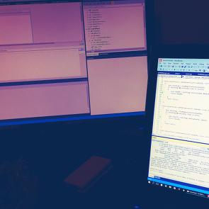
The creator of the Mirobot has a write-up on a Raspberry Pi-based bulk Arduino programming jig. The setup was created to assist in the building of Mirobots for fulfilling his Kickstarter campaign.
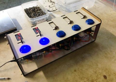
It's essentially as Raspberry Pi that drives 5 USB to serial devices that in turn program an Arduino Pro mini. The bulk programmer uses a lighted button to initiate programming and give status/error/success feedback for each device. All of this is contained in a custom laser cut frame.
Using some custom node.js code, he was able have the programmer program each Arduino independently and concurrently, so that by the time he has mounted the last device, the first one is finished programming.
We're nuts for indie automation and metahacks here at Anibit, so his setup is very impressive and innovative. The Mirobot is a really neat looking device too!
This is something we've been cooking for a while, and we're exited to finally unleash this on the masses.
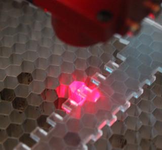
We've developed a system for making parametrized box designs for laser cutting. I've taken a few permutations of parameters and released them in the form of an auto-generated web-app at https://anibit.com/box
You can even download a dxf file template for use if you have access to a laser cutter and would like to make your own.
The whole thing is is alpha right now, there may be problems with the design, but what we've tested so far mostly works.
Please, we really want to hear feedback about this, we have big plans to expand it to cover more things.
Is a standard "telephone" style input pad not enough for ya? This just may be the keypad for your next project!
This keypad is similar in operation to our 3x4 button pad, but has an extra column with 4 additional buttons, labeled "A", "B", "C", "D".
It features an adhesive backing, so you can permanently attach it to your project. The input pad is 70mm wide and 77mm high. The 8-line ribbon cable is approximately 65mm long and is terminated with a 8x1 female header, 15mm in length and 20mm wide with standard 2.54 (0.1") spacing.
The ESP8266 ( get them [here] ) is a very low-cost WiFi to serial board for makers that lets you create "Internet of Things" (aka "IoT") devices with low-end hardware, such as Arduinos, mbed, and raw microcontrollers.
You can use a UART device on your Arduino, etc to talk to this board and communicate over to other devices, computers or websites. The hardware on the ESP8266 takes care of all the overhead needed to implement Wifi. You use an "AT" style communication over the serial UART to interact with it, reminiscent of the way dial-up modems over phone lines used to work.
All content copyright Anibit Technology. LLC, or used with permission. This site requires the use of browser cookies for full functionality. See our privacy statement for more information.